Tori Electromechanical
Santa Clarita California

Restoration and repair of old school devices.
USA,  German and Japanese. 

.
Home Rebuild Gallery Products Documents Contact About           

Restoration and repair service on any good machine

Rebuilding Bosch 0010915201 Pump

First draft Feb 2014
Rev. Mar 8 2014

Audience: Document is intended for those interested in seeing how I rebuild this electric fuel pump.

Disclaimer: This is not a guide for rebuilding. It only serves to illustrate the procedure I use. It may help you to decide if rebuilding is for you or if purchasing one already rebuilt is a better option. You may also email me about a quote for rebuilding your pump.

Kudos: George Desiderio and  Bob Smith for their excellent fuel pump articles on www.sl113.org and Bob Boloori of VintageEuroParts.com

This article is incomplete - Under construction - ETA May 2014.  Your comments are encouraged and welcome
.
Determine first if the pump runs by testing with 12 VDC . A battery or charger will work just fine or any power supply that will deliver 12 VDC  at least 5 Amperes. Care here that the pump does not eject gasoline creating a dangerous situation.

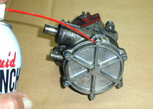
Apply penetrating lube to the fasteners and let sit overnight if possible. 
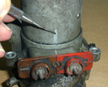
Mark the motor can relative to the brush housing, and the bottom cover. Use a deep scribe or a center-punch. If you get the motor can rotated on re-assembly the pump will run in reverse.

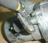
Using a good, sharp slotted screwdriver remove the bottom plate. If the screws are corroded in place either tap the back of the driver with a hammer a few times or use a hand held impact driver. If you are using an impact driver I have found it works to use a good size hammer and hit the driver gently several times. You will see the head turn slightly for each tap. Breaking a screw happens. 

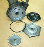
Tap the bottom cover with a plastic hammer to remove. You may need to carefully pry at the seam for a while with a sharp blade. If you raise burs they can be removed later.

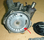
When the cover is removed you will see the turbine and cover o-ring seal. Remove the turbine and note that the pointed end of its blades point toward the pump, not the bottom cover plate. If you get this wrong on re-assembly, the pump pressure will be low. Note also the missing blades on this one. It cannot be reused.

The turbine generally does not come off easily and it is fragile! Try using two hooks to rock it off the motor drive shaft. If it's stuck because the gasoline has jelled try this; Fill a saucepan with water and a little laundry detergent enough to cover the bottom of the pump. I let the soapy water come to a boil, reduce heat and simmer for 30 minutes. The soup reeks. You'll get booted out of the kitchen. Also discolors the casting a little. 

The pump will be hot when you remove it. Use care that the turbine does not fall off and break. I've had to cook these pumps outside on a hotplate sometimes for an hour to remove the jell and turbine
.
.
.
.


.
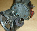
Use some sharp jaw pliers to remove the rubber dampeners. Grab them at the bottom metal mount. The studs are threaded. Then you can remove the three screws holding the motor assembly to the pump body. 


Pull the motor assembly from the pump housing. Note the o-ring seals. 


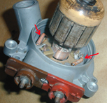
By removing the two M4 nuts and washers from the bottom side of the brush housing, the motor stator magnet canister is freed and can be removed. The magnets are strong and it takes some control to pull it straight off. Use care here that you don't damage the two coil chokes as the studs pass by. There may be thrust washers on the armature shaft as you pull the canister off. They may stick to the rear bearing or be pulled off by the magnets. Look carefully to find them. Some pumps don't have them. If yours does note how many and record it. There may be three. A fiber shim (0,03) sandwiched between two 0,30mm steel shims. 


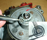
Turn the e-clip located inside the motor "snout" toward the relief. It can then be easily removed using a small, flat-blade screwdriver. There should a stack-up at least three thrust washers under the e-clip. Remove them without deforming or bending. Note the types of thrust washers and how many there are. Record it. This is especially important if you are not going to turn the commutator on a lathe. You will probably find two or three 0,30mm thick steel shims,  a 1.0mm steel shim and possibly a 0,30 fiber shim. If the fiber shim is worn or frayed you can use a steel replacement supplied with any good rebuild kit. 


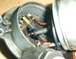
There is another e-clip and shim set on the armature shaft inside the brush housing. As you remove the commutator, push the brushes back and angle the shaft to clear the brushes. Again note the shim stack-up. Record it. There will probably be three. A fiber shim (0,03) sandwiched between two 0,30mm steel shims. 
Note: This picture shows the canister still on the armature. If you followed the procedure so far it will have already been removed. 


.
.


If you have good equipment deserving of restoration, please contact me for service.
Tori Anne Yaworski - Tori Electromechanical  - In the Valencia Industrial Center, Santa Clarita, CA
         tori127@toritinker.com

Page last revised: February 1, 2014